
Instructions
Instructions
Correct installation and maintenance are related to fan performance and service life. For this reason, please read this manual carefully and operate as required.
1. Installation overview
 1. Installation place of the fan
⑴Please pay attention to the following points when selecting the installation place of the fan:
a If the fan is in the open air, it should be protected by protective facilities;
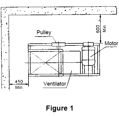
b The ventilator should be placed in a place convenient for management and monitoring (Figure 1);
c The installation site should have a solid foundation.
Especially for the ventilator installed on the elevated structure, the installation place should be a structure that does not induce vibration.
 2. Installation space requirements of the fan
The area of the site for installing the ventilators, the following points should be considered when estimating:
⑴ It does not harm the normal operation of other adjacent machines;
⑵ It is safe and convenient to overhaul the ventilator;
⑶ When disassembling the impeller, there should be enough space.
3. Various installation methods and requirements
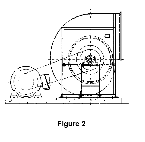
⑴ Installation on the ground
The ventilator is generally installed on a concrete foundation, but small ventilator with a smaller model and lower motor power can also be installed directly on the ground without making a foundation. Even so, attention should be paid to the strength of the foundation (Figure 2).
⑵Installation on the floor (high bench)
Full attention should be paid to the rigidity and strength of the installation area to avoid resonance when the fan is running, otherwise reinforcement measures must be taken (Figure 3A).
⑶Ventilator installed in the box
In order to avoid vibration of the fan due to insufficient structural rigidity and strength, full attention must be paid to the strength of the installation frame. Especially when using anti-vibration rubber (spring) and other anti-vibration materials, be sure to install the fan and the motor on the same chassis (Figure 3B).
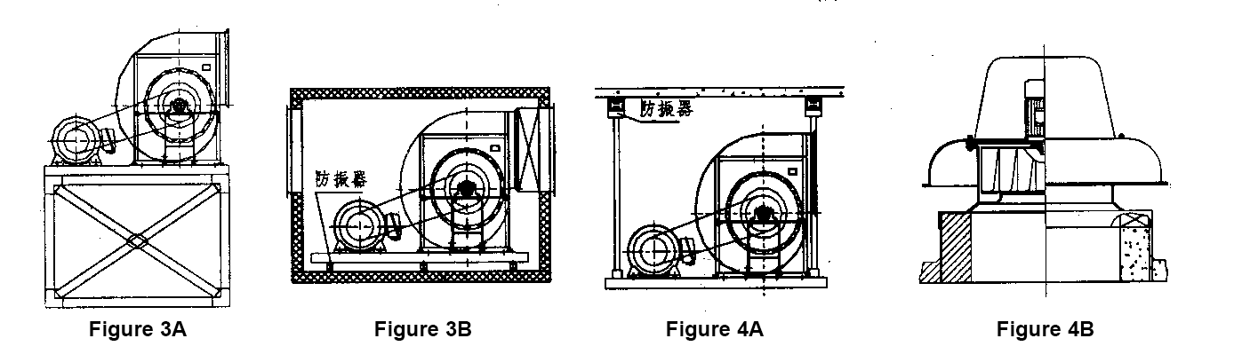
4. When hoisting on the ceiling
Small ventilators can simply be installed with bolts (Figure 4A). For medium-sized ventilators, the hoisting type should use a welded frame structure to install the fan, and try to install it on the ground.
⑴Wall-mounted fan (exhaust fan) The installation wall must be strong.
⑵Roof installation
For the installation of sub-roof fans, full consideration should be given to the impact of external storms, rain and snow on the fans (Figure 4B).
2. Basic
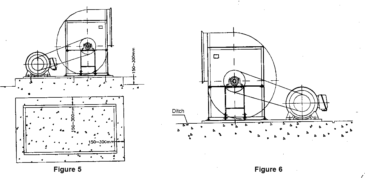
1. Concrete foundation
⑴ The plane size of the concrete foundation is at least 150-300 mm larger than the outer edge of the fan chassis. The foundation of a small ventilator is a small value, but the thickness of the foundation is at least 150 mm, and the basis weight is about 5-10 times greater than the total weight of the ventilator (Figure 5).
⑵Considering that the chassis of the ventilator will not be corroded by accumulated water, drainage ditch should be set around the foundation (Figure 6).
⑶ The foundation surface should be flat and smooth, and fully consider the position of the embedded bolt holes.
⑷The space between the foundation surface and the fan chassis should be adjusted with gaskets, etc., to make it fully contact and fix.
2. Use of anti-vibration components
⑴ When using anti-vibration components, the fan and motor must be installed together on a common chassis with sufficient rigidity.
⑵In order to make each anti-vibration component bear the force uniformly, the foundation plane should be level. If some components float under the fan chassis, it may cause abnormal vibration of the fan.
⑶ When using anti-vibration components, be sure to install expansion (expansion) joints on the ventilator interface pipe.
⑷The impeller may accumulate dust or foreign matter adhere, which will greatly affect (destroy) the dynamic balance of the impeller. In this case, it is not appropriate to use anti-vibration elements on the foundation.
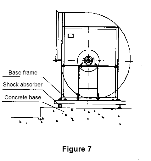 3. Anti-vibration components
The anti-vibration components of the ventilator include anti-vibration gaskets, anti-vibration rubber, anti-vibration springs, etc. (Figure 7).
⑴Anti-vibration rubber, anti-vibration spring
The weight of the fan and fan frequency operation, select an appropriate anti-vibration element member which is better. If the fan is running at low speed or the load is light, anti-vibration rubber can be used for this .
Three, handling, storage and retention
Full attention has been paid to the centerline calibration and dynamic balance of the ventilator before leaving the factory, and it is allowed to leave the factory only after it has passed the operation. Therefore, the fan should not be scratched or even deformed when transporting it on the customer site.
1. Component inspection
⑴ Check whether the fan is damaged, deformed, and the paint is in good condition.
⑵Whether the components and spare parts of the fan are mixed or omitted, and whether the quantity is consistent before and after handling
2. Hoisting and handling
⑴ Please use the lifting hole (hook) when the fan is transported, placed and hoisted;
⑵When hoisting the work with ropes and wire ropes, the ropes should be as long as possible, and the rigging points should be arranged reasonably to prevent the wind turbine from deforming.
⑶ When hoisting the split casing and rotor, pay attention to the contact part of the rope and the workpiece should be filled with cloth or soft rubber, especially the impeller and shaft. Even slight deformation may cause the reduction of dynamic balance accuracy, resulting in the fan during operation. vibration.
⑷V-belt pulleys, butter nozzles, etc. are vulnerable to injury during hoisting, so you should pay full attention when installing rigging.
⑸ When the equipment is moving, it will cause the shaft and belt wheel: the impeller has a great impulse, so please pay attention to the shaft
Acceptance is not in the palm of his hand.
3. Keep
⑴Before the fan is installed, the fan should be placed in a ventilated and dry place and checked regularly to prevent rust and damage.
⑵ During the storage period, the fan shall be cranked at least twice a month, at least 10 revolutions each time. According to the feeling when turning, pay attention to the lubrication of the bearing. Secondly, after opening and closing the adjustable door and other rotatable parts several times, inject lubricant when necessary to prevent rust.
4. Even if the installation of the fan has been completed, but the operation has been stopped for a long time, in addition to the procedures described above, the bearing cover should be opened to carefully check the lubrication of the bearing.
Four, installation method
Before the fan leaves the factory, the manufacturer has aligned the fan and motor, and then leaves the factory. However, due to transportation reasons and the base itself will inevitably produce elastic deformation, so after the fan is installed on the foundation, it should be aligned again.
1. Correct
⑴General situation
a In principle, the level of the fan is based on the shaft. If the axial flow fan is installed vertically (vertical), the machining surface of the V-belt wheel and impeller hub can also be used as the reference.
b. The fan is placed on a flat concrete foundation to check the level with a level gauge. For level calibration, a gasket can be placed between the fan and the foundation. Then, pour cement grout to make the joint surface fully contact. At the same time, cement grout can be injected into the reserved holes of the foundation bolts, and the bolts can be vertical and fixed.
c. Foundation bolts should be evenly tightened. Overtightening of local bolts will often cause the shaft center to shift and cause bearing damage.
⑵The fan in the assembly box
a The fan is installed in the assembly box, and the bearing should be considered more convenient; and the whole fan should be installed in the box as it is (do not disassemble).
b The assembly box should be equipped with inspection windows or doors for replacing and inspecting bearings.
2. Installation of bearing seat
When tightening the mounting bolts, be careful not to cause undue axial force on the bearing in the axial direction.
⑴The situation of using the bearing seat
The bolt ② on the bearing seat is tightened according to the procedure shown in (Figure 8). After the bolts ① on the two sides of the bottom are tightened, first slowly tighten the bolts on the free side of the horizontally split bearing seat. The non-free side of the bearing is generally taken on the side of the motor, but for E-type transmission and hot air blowers Some take the one on the non-motor side, and then tighten the non-free side bolt.
High temperature fans should fully consider the thermal expansion and elongation of the shaft.
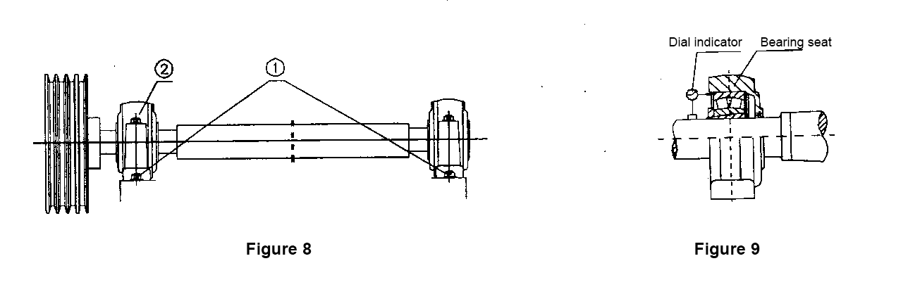
Alignment method of bearing and shaft
Remove the bearing side cover and install a dial indicator on the shaft, and take the outer ring of the bearing at the measuring point (if it is impossible to take the outer ring, you can take the part processed on the side of the bearing seat). Rotate the shaft lightly, read the values of the up, down, left and right dial gauges, and write down: take 1/2 of the difference between the up and down or left and right readings, and set the deflection value as T. If the distance between the side point and the shaft center is R, the inclination value of the bearing to the shaft can be obtained according to the T/R value (Figure 9).
Table 1 Allowable inclination of bearing
|
Bearing type |
Allowable gradient (series/degree) |
||||||||
|
Double row self-aligning ball bearing |
12/2° |
13/2.5° |
14/2.5° |
22/2° |
23/2.5° |
|
|
|
|
|
Double row spherical roller bearings |
213/1° |
222/1.5° |
223/2° |
230/1.5° |
231/1.5° |
232/2.5° |
339/1.5° |
240/2° |
241/2.5° |
Note: Table 1 shows the allowable misalignment and allowable inclination when the inner ring rotates under normal load and working conditions. Whether the given value can be safely achieved depends on conditions such as bearing configuration design and seal type.
⑵The use of bearing unit
The bearing unit has self-aligning performance, so it has an alignment range of 2° (l° with bearing cover). However, due to the simple structure of the unit bracket, its axial allowable capacity is small. Please pay attention to this when installing:
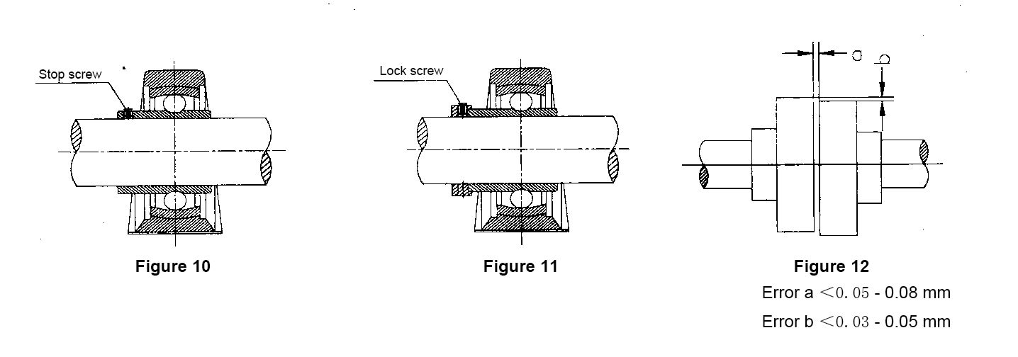
a Set screw radial ball bearing unit
Use this type of bearing unit, after adjusting the spacing between the bearings, drilling and positioning. Therefore, it should be noted that the positioning hole should be consistent with the required installation position. During the daily use of the fan, pay attention to whether the screw is loose and whether the position changes; otherwise, vibration will occur during operation, which will cause relative movement between the bearing inner sleeve and the shaft (Figure 10).
b Eccentric fixed wheel radial ball bearing unit
It uses the oblique wedge principle to fix the bearing on the shaft, and the effect is better. Install the eccentric ring on the eccentric extension part and rotate it along the rotation direction of the machine shaft until it is locked (Figure 11), and pay attention to tighten the anti-loosening screw, otherwise it will loosen.
If the direction of rotation of the crankshaft is unknown, it is recommended to lock the bearings at both ends of the shaft in opposite directions.
3. Confirm the motor rotation
⑴ When installing the motor, turn it by hand to confirm that there is no abnormality.
⑵Before hanging the V-belt or installing the coupling column, confirm that the motor steering meets the fan steering requirements.
4. V-belt and V-belt
Before the fan test operation, check the belt and pulley, align the center between the pulleys and adjust the belt tension.
For details, please refer to the maintenance and inspection of V-belt pulley and V-belt in Chapter 6 "Maintenance and Management".
5. Coupling alignment
When installing the fan driven by the coupling, the coupling can be used for alignment. First, remove the bolts of the coupling, remove the pin, and check the deviation of the shaft center and the end surface while rotating the flanges of the coupling on both sides by hand. In most cases, the up, down, left, and right swing deviation adjusts the range shown in Figure 12.
6. Pipe connection
⑴ In principle, the fan and the pipeline should be connected by a flexible pipe, and the bolts should be evenly tightened and the centers should be consistent. Otherwise, the casing may be deformed and the air inlet will rub against the call wheel.
⑵Before connecting the pipe to the fan, check the inside carefully, and remove any foreign matter.
(3) If the fan inlet is not connected to the pipe, a protective net with sufficient strength should be installed on the side of the suction inlet to prevent foreign matter from being sucked into the fan.
⑷The gap between the impeller and the air inlet
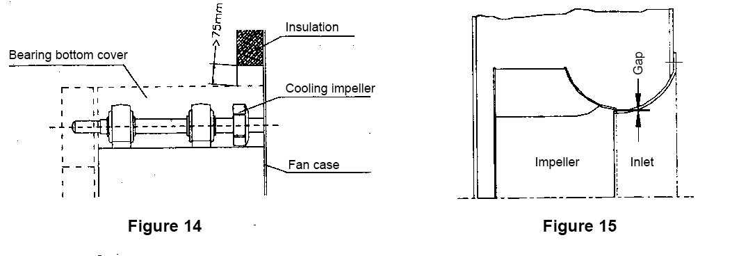
After installation, check and confirm that the up and down, left and right clearances between the impeller and the air inlet are basically uniform (Figure 15).
7. Installation of hot air blower
Should focus on preventing the impact of thermal expansion on fan operation.
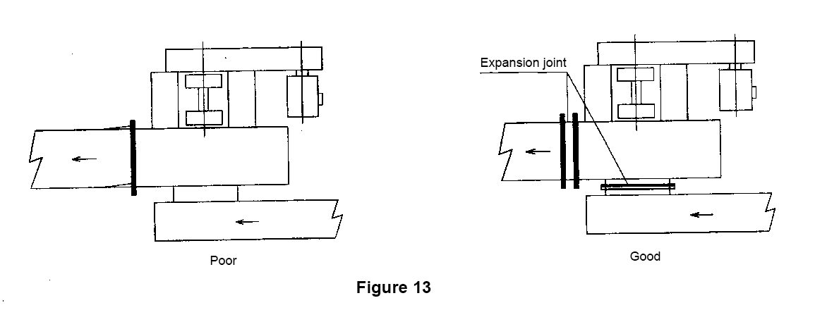
⑴Inlet and outlet pipeline connection
The thermal stress caused by temperature changes should not be directly borne by the fan body, and expansion joints must be used. For a steel-steel structured pipe with a temperature change of 100°C per 1000mm length, the deformation is about 1.3mm; if the inlet and outlet expansion force is directly applied to the fan, it will cause a large deformation to cause the impeller and the air inlet element to rub (Figure 13).
⑵Cooling of bearing parts
In order to reduce the influence of medium temperature on the bearing, a heat exhaust fan should be equipped between the casing and the bearing to protect the bearing (for gas temperature less than 250℃). For the heat exhaust fan, because the surrounding air is less cooled, please be careful not to block the circulation part at the outer end of the fan (Figure 14)
Five, test run
Carry out trial run according to the following procedure.
1. Check
The bolts and nuts should be locked evenly and symmetrically one by one; otherwise, if the positions are too tight or too loose, it will cause air leakage, noise and vibration, and cause shaft wear and bearing damage.
2. Come on
⑴ For bearings that use grease, proper amount of grease has been added to the fan bearings before leaving the factory. If you want to replenish the grease again, you should ensure the quality of the grease. If the lubricating grease is of poor quality or even unclean, it will cause bearing damage.
⑵In the case of thin oil lubrication, please add oil according to the instructions of the oil standard.
⑶ Replenishing lubricating oil for bearings, please follow the instructions described in Chapter 6 "Maintenance and Management".
3. Hand turn
When turning the impeller by hand, please pay attention to the following points:
⑴Listen to the sound
The presence or absence of the sound of touching, rubbing, or touching foreign objects.
⑵Other
a Tension of triangle tape;
b Whether the hand feel is too heavy or sometimes light and heavy when cranking.
4. Air supply system
⑴ Whether the components in the device are normally configured as required.
⑵ Whether there is any foreign matter near the air inlet and outlet or inside the fan device.
⑶Whether there are unsafe factors (such as things being sucked in or blown off) near the inlet and outlet of the fan when the air is supplied or induced.
5. Electrical wiring
⑴ Whether the system has short-circuit connectors or easily-opened connectors.
⑵ Carefully check the connection in the junction box.
6. Start
⑴After confirming that the ventilation system, electrical system and other machinery are in normal state, it can be put into operation. First of all, turn on the switch for 3 to 6 seconds and then cut it off, confirm its steering, whether there is abnormal sound, vibration, etc.
⑵ If abnormal conditions are found during instantaneous operation, check the unit according to the aforementioned process and make corrections before proceeding with trial operation.
⑶ Generally, the current when the fan and motor starts is 5 to 7 times the rated current, and then gradually decreases. If the current drop speed is too slow, stop running and check the motor power supply system.
7. Operation confirmation
⑴According to the indicated value of the ammeter, slowly adjust the regulating door to make the opening and closing angle reach the specified position.
a Record current and voltage values;
b Check the vibration, temperature and sound of the bearing;
c Pay attention to the heating of the motor. Generally, the allowable surface temperature of the motor is not more than 80℃.
⑵Please pay attention to the following matters within one week after the fan starts running.
a Rubbing of the rotating part:
① The collision between the impeller and the inlet;
②The friction between the impeller and the casing:
③The friction between the shaft and the through part of the casing;
④The friction between the triangle tape and the bearing seat:
⑤The friction between the triangle tape and the belt cover.
b State of triangle tape
①Abrasion of triangle tape;
②The tension of triangle tape.
c The swing of the coupling (whether the coaxiality is intact)
d other
①Whether the foreign body is inhaled or not;
② Vibration of the fan body.
⑶ After trial operation, the tightness of triangle tape should be adjusted. The new triangle tape will stretch. If the above situation occurs, stop and adjust its tightness.
⑷In addition, the lubrication state of the bearing and the state of lubricating grease should be checked.
⑸ If there is no cranking device for the high temperature fan, the air temperature in the blower can only be stopped after it drops to 100°C.
⑹The fan must not arbitrarily increase the speed to change the performance parameters of the fan, otherwise accidents may occur.
Six, maintenance and management
In order to make the fan continuous operation without failure, maintenance and management are very important. Before an accident occurs, there must be signs or some abnormal phenomena. If you regularly check carefully, you can prevent problems before they happen.
The inspection of the fan is divided into regular and daily. If the bearing transmission parts are abnormal, it will cause abnormal noise, vibration and temperature rise. The inspection of the wind turbine should pay attention to the above situation, and the daily inspection is an important means to detect the accident seedlings early.
1. Regular inspection
⑴ During the trial operation, if the fan runs smoothly, and the original use conditions remain unchanged thereafter, it can be prevented indirectly for 1 to 3 weeks according to the periodic inspection table in Table 2, and regular inspections are carried out.
⑵The purpose of regular inspection is to ensure the normal operation of the fan, eliminate hidden dangers and prevent them before they occur, and accumulate information on the operation of the fan.
Table 2 Regular maintenance table
|
Overhaul point |
project |
Check content |
|
meter |
Ammeter, |
l. Is there any fault in the meter? |
|
chassis |
vibration |
Whether the welding on the surface of the case is collapsed and |
|
Air leak |
Is the seal on the connecting and dividing surface of the chassis damaged? |
|
|
impeller |
Friction with the case |
Is the air inlet gap uniform? |
|
vibration |
Is the pollution (trifoliate, fouling) serious? |
|
|
Impeller deformation |
Is the corrosion, abrasion, and bending deformation serious? |
|
|
Shaft deformation |
Is the bearing installation part and shaft sleeve installation damaged? |
|
|
Bearing |
Vibration, heat, sound |
Are the bolts loose? |
|
basis |
vibration |
Whether the anchor bolts are loose and |
|
Triangle tape wheel |
Floating, heating |
Is the triangle tape slippery? |
Note: As the above items are connected to each other, please pay attention when checking. For example: If the cause of vibration due to bearing damage.
(3) In order to find the cause of the malfunction of the fan during operation, please investigate according to Table 3. Table 3 is a table to find out the cause of the cause more easily from the surface phenomenon.
Table 3 Discovery and treatment of abnormal conditions
|
abnormal situation |
the reason |
deal with |
|
The air volume is too small |
Design static pressure is too small |
Reevaluate the design of the device |
|
System air duct leaks |
Adjust after inspection |
|
|
Adjust the door opening too small |
Adjustment |
|
|
Wrong steering |
Correct in time |
|
|
Slipping by the sub-triangular tape, the speed is reduced |
Adjust the tension of triangle tape |
|
|
Motor overload |
Triangle tape is too tight |
Adjust the tension of triangle tape |
|
Incorrect motor selection |
Swap |
|
|
Design static pressure is too large |
Reduce speed |
|
|
Poor adjustment of the regulating door |
readjust |
|
|
Motor failure |
Repair or exchange |
|
|
Abnormal sound |
Rolling bearing "pimple sound" |
Rubbish mixed into bearings: replace |
|
"Cackling, clattering" |
Cracks or scars: swap |
|
|
"Hiccups or clicks" |
Add oil or change grease |
|
|
"Right now sound" |
Shaft wear: adjust shaft |
|
|
Impeller rubbing |
Tighten and adjust bolts, trim contact parts |
|
|
Bearing lock nut is too loose |
Afterburner lock |
|
|
Shaft movement |
Find out the reason and fix it |
|
|
Air surge |
|
|
|
Improper fan selection |
Modification of the device, and then optional fan |
|
|
Poor piping system |
System remodeling |
|
|
Bad pipe connection |
Re-adjust |
|
|
Mixed with foreign matter |
Remove |
|
|
Wind speed is too high |
Retrofit the pipeline system |
|
|
The temperature rises sharply |
Bearing heat due to failure |
Refer to the abnormal sound item |
|
Poor bearing installation |
Adjust the center and tighten the mounting bolts |
|
|
Impeller poor dynamic balance |
Adjust the impeller dynamic balance |
|
|
Lubricating grease |
Remove the excess part (filling 1/3~l/2 in the bearing seat is better) |
|
|
Overfilling of grease |
Decompose and wash, replace with qualified new grease |
|
|
Insufficient amount of grease, deterioration, |
Decompose and wash, replace with qualified new grease |
|
|
Improper selection of grease |
Adjust the load and repair the motor insulation |
|
|
Motor overload, poor insulation |
Adjust or reinstall |
|
|
Sealing part rubbing |
|
|
|
vibration |
Insufficient material strength (rigidity) of foundation |
Check the basic condition |
|
Poor foundation design |
Check the basic condition |
|
|
Loose foundation bolts |
Lock |
|
|
Impeller imbalance (garbage, paint and other foreign matter adhere to the impeller) |
Clean the impeller |
|
|
Bearing damage |
Participating sound, temperature rise item |
|
|
Shaft wear |
Swap |
|
|
Triangular tape slips |
Adjust the tightness of the triangle tape |
|
|
Transmission of external vibration to the fan |
Use anti-vibration pads to prevent vibration with flexible pipes |
|
|
Coupling swing out of tolerance |
Recalibrate |
|
|
Improper fan selection |
Reselection |
Note: The above abnormal sound response is judged by experienced technicians.
2. Daily inspection
The abnormal condition of the fan is generally abnormal sound, vibration or temperature rise, for which daily inspection is very important.
⑴Vibration
Take the centerline of the motor and fan bearing seat as the standard, measure and record the vibration values in the X, Y, and Z directions, and make judgments based on the standard JB/T8689-1998 "Ventilator Vibration Detection and Limits". The eligibility criterion of this standard is "the effective value of the vibration speed of the fan (root mean square speed Vrms, Vrms≤4.6mm/s for rigid supports, Vrms≤7.1mm/s for flexible supports)." The influence of the external or surrounding environment on the base or test bench should meet the following requirements: the difference between the vibration speed of the fan during operation and the vibration speed of the fan when it is stationary must be more than 3 times, when the difference is less than this value, the fan should be avoided Measures of external influence." Otherwise, appropriate amendments will be made (also through negotiation).
·Do not want the fan to run below the standard, even if it is recognized as a fan that can still be used.
⑵ Sound
In addition to the normal sound generated during operation of the ventilator, if any abnormal sound occurs, the cause should be determined immediately. Please pay attention to belt slippage, loose connection, foreign matter intrusion, bearing, motor failure, etc. In particular, the inspection of bearings, such as poor lubrication, bearing rupture, etc., can avoid accidents if detected early.
⑶Temperature
Please pay attention to the temperature of the fan bearing seat and motor housing. If it is used to indicate that the touch surface can only last for 3 to 4 seconds, the surface temperature is about 60℃. In order to have an accurate judgment on the abnormal temperature rise, it can be accurately measured with the meter.
After the fan is stopped, if the temperature of the V-belt is too high, it may be caused by the slip of the V-belt. The tension should be measured and adjusted.
3. Maintenance and inspection of bearings
⑴For bearing performance, please refer to the corresponding sample
⑵Installation and disassembly of bearing
Please refer to the relevant content of this manual, combined with the bearing manufacturer's manual.
⑶ Bearing life
According to the design method of bearing dynamic and static load and rated life and referring to relevant domestic and foreign standards, our design standard for bearing life is generally 20,000 to 30,000 hours.
⑷Lubricant brand, replenishment interval, filling amount
a Grease, oil grade
The general occasions are the same as the heat-resistant conditions, as shown in Table 4, but for high-speed and high-temperature environments, special consideration is required for the grade.
Table 4
|
species |
characteristic |
Standard |
Codename |
name |
Remarks |
|
grease |
General use |
GB491-65 |
ZG-2 |
Calcium base grease |
|
|
Industry General |
/ |
LGMT3 |
Lithium soap/mineral oil |
Imported grease |
|
|
Heat resistant |
SY1407-35 |
ZFGM |
Complex calcium grease |
|
|
|
Hardy |
Q/SY1412-75 |
ZL-1 |
Lithium Grease |
|
|
|
lubricating oil |
General use |
G443-64 |
HJ |
Machinery oil |
|
|
For compressor |
|
HS-13 |
Compressor oil |
Heat resistant |
b Grease replenishment interval
Since the bearing unit and the bearing seat can seal the grease in the bearing cavity, the running condition is good, and the grease can maintain a longer running time. But in the case of harsh operating environment, please add grease according to Table 5. Especially for 24 hours continuous operation, where dust and humidity are obvious, the supplementary interval in the following table 5 should be shortened by half. Secondly, the bearing seat assembly should be equipped with a protective cover.
Grease should be injected evenly and slowly under low-speed rotation or manual cranking.
The amount of grease filled should be about l/3~2/3 of the volume of the bearing or housing cavity. Excessive filling of grease will also adversely affect the operation of the bearing.
Table 5 Grease filling prevention of bearing unit and bearing seat
|
Bearing operating temperature ℃ |
Speed r/min |
||
|
|
Below 1500 |
3000 or less |
Over 3000 |
|
60 or less |
4 months |
3 months |
2 months |
|
70 or less |
2 months |
1.5 months |
1 month |
|
Below 80 |
1 month |
0.5 month |
0.5 month |
c Unpacking inspection and grease replacement of bearing set
Even if the fan is running normally, open the bearing box cover for inspection at least once a year (except for the bearing unit).
·Are there any scars or cracks on all surfaces and parts of the bearing?
·The matching of the bearing outer ring and the bearing box mating surface, the free end swimming, whether the condition is normal
·The center of the shaft and the bearing seat, whether the assembly bolts are loose, whether the gap adjustment spacers, etc. are normal
·After the bearing is cleaned, add new grease as required
⑸ Operating temperature
Generally, it is normal that the ambient temperature on the surface of the bearing seat is at room temperature plus 40°C or less than 70°C. If it exceeds 70°C, it must be disposed of in time.
4. Maintenance and inspection of coupling
⑴ The swing deviation should be strictly controlled below the requirements
⑵Pin pins with accurate wear loss should be replaced in time
5. Maintenance and inspection of belts and pulleys
⑴The installation method of triangle tape
a In the case of multi-groove triangular tape, please pay attention to whether the grade of the tape and the shape and size of the tape are within the allowable error range (confirmation of the tape group).
b If the tape length deviation is large, it will affect the fatigue of the tape, the vibration and the life of the unit.
Please do not mix new and old tapes.
c When installing the tape, loosen the support bolts under the motor base to make the center of the second V-belt narrow and install. If the tape is not pryed into the scull according to the above method, it will cause internal damage to the tape and cause early deflection. The belt is broken.
d Please note that the surface of the tape should not be stained with oil or dust, especially the adhesion of oil will cause the tape to slip during operation, which will not only fail to fully exert its power transmission function, but also shorten the life of the tape due to heat.
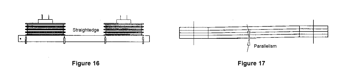
⑵ Center adjustment of V-belt pulley (Figure 16)
If the centers of the two axes of the V-belt are installed parallel to the standard, it will cause unilateral wear of the V-belt, and the durability of the tape will be significantly reduced. Please adjust the parallelism of the V-belt within 1/3° (Figure 17).
⑶Adjustment of tape tension
The elongation of the tape can reach 80-90% (initial stretch) of the total elongation of the tape within 24 hours after the operation starts.
For this reason, once a day for 2 days after the start of operation, and once a week thereafter, please check the belt tension. If the tape is too loose, it is easy to slip, causing wear and tear and resulting in scrap. If the tape is too tight, it will cause abnormal loads on the shaft and bearings, so the tape must be properly tightened.
The recommended tape tension adjustment cycle is shown in Table 6
Table 6
|
time |
Start of test run |
In the next two weeks |
In the next two months |
Every two months thereafter |
|
Number of adjustments |
Should be once a day for 2 days |
once a week |
Once a month |
once |
a General requirements for adjustment of triangle tape tension
①Push the center of the tape with your fingertips with proper dusting force
②The loose side has moderate curvature during operation
③There is no slipping sound when starting,
④The V-belt does not heat up
b Procedure for adjusting triangle tape
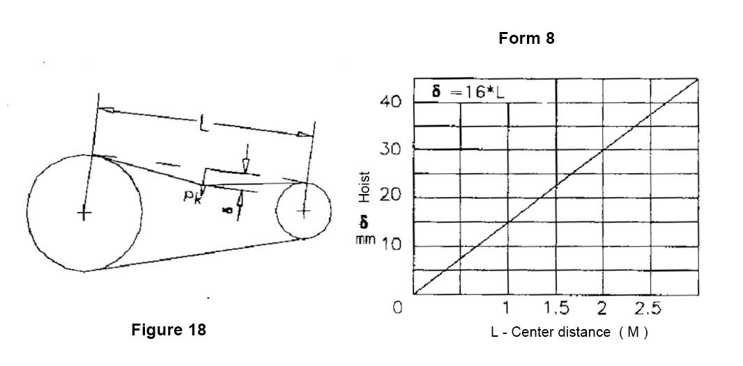
① As shown in Figure 18, give the specified load Pk apparent common deflection in the center between the two center distances of the V-belt pulley.
Table 7 lists the approximate value Pk value of the load. Since the Pk value is related to the transmission power and the speed of the tape, if it is necessary to further understand the exact value, please consult the tape manufacturer.
②According to Table 8, the appropriate deflection δ of the tape can be known, which can be used to determine the tightness of the tape.
③Life of V-belt pulley
Due to the insufficient tension of the triangular belt, the belt slips and the belt wheel wears sharply, which reduces the friction coefficient of the belt groove and increases the groove depth. Therefore, after the new belt is installed, the appearance of the belt is very low compared to the outer diameter of the pulley. In this case, even if the belt tension is normal, there is no slipping sound when starting, but the belt wears a lot during operation, so this type of V-belt wheel should be replaced.
④Life of triangle tape
With continuous operation under suitable tension, the life of the tape can generally reach more than 8000 hours, and it is replaced about once a year. If the surface of the tape is worn and cracks grow, this is when the life of the tape will end.
Table 7 The given lifting weight Pk
| Belt type | Small pulley diameter (mm) | Pk(kg) |
| Type A | 80~140 | 2.5~3.6 |
| 140~200 | 3.6~4.6 | |
| Type B | 112~240 | 4.6~6.6 |
| 240~320 | 6.6~8.7 | |
| Type C | 220~360 | 8.7~11.7 |
| 360~500 | 11.7~15.3 | |
| Type D | >300 | 15.3~20.4 |
6. About the daily maintenance of the motor
⑴The operating environment should be kept dry, the surface of the motor should be kept clean, and the air inlet should not be obstructed by foreign objects such as dust, fibers, etc. The motor should be properly grounded and wired according to the wiring method specified in the nameplate or junction box. Before use, install a thermal protection device that causes the motor to overheat due to abnormal power supply.
(2) Good lubrication of the motor should be ensured during operation. Normally, the motor should be supplemented or replaced when the motor runs for about 3000-5000h (specifically based on its use, the closed bearing does not need to be replaced during the service life of the grease). During the process, if the bearing is overheated or the grease has deteriorated, the grease should be replaced in time (fill 1/2 or 2/3 of the cavity between the inner and outer rings of the bearing with ZL-3 lithium grease).
⑶ When the life of the motor bearing ends, the vibration and noise of the motor will increase significantly during operation, and the bearing should be replaced in time.
Safety warning
1. Since the fan has rotating parts and generates heat, the operator and external objects should not be near the air inlet and outlet of the fan.
2. During normal operation, do not touch the fan and its motor.
3. Operation, installation and maintenance should strictly follow the safe operation regulations specified in the instruction manual, and the operation of the fan should not exceed the maximum operating temperature, maximum operating speed and vibration requirements.
4. Those who have not read and understood this manual in detail and are not familiar with the operating specifications are not allowed to work.
5. The user is responsible for installing additional protective devices, and refer to the manufacturer's instruction manual.
6. Before starting maintenance, turn off the switch and cut off all power. During maintenance, the impeller, the cleaning door and the separation surface of the casing should be firmly connected. Otherwise, when the fan is running, the loose parts will be thrown away due to the increase in the internal pressure of the fan.
7. When the fan impeller reverses, it must not start.
8. The safety requirements and qualified use conditions for operation, installation, commissioning and maintenance specified in the instruction manual should be followed, otherwise, the failure may cause damage to the fan and casualties.
Shanghai Yingda Fan Co., Ltd.